POPULACE
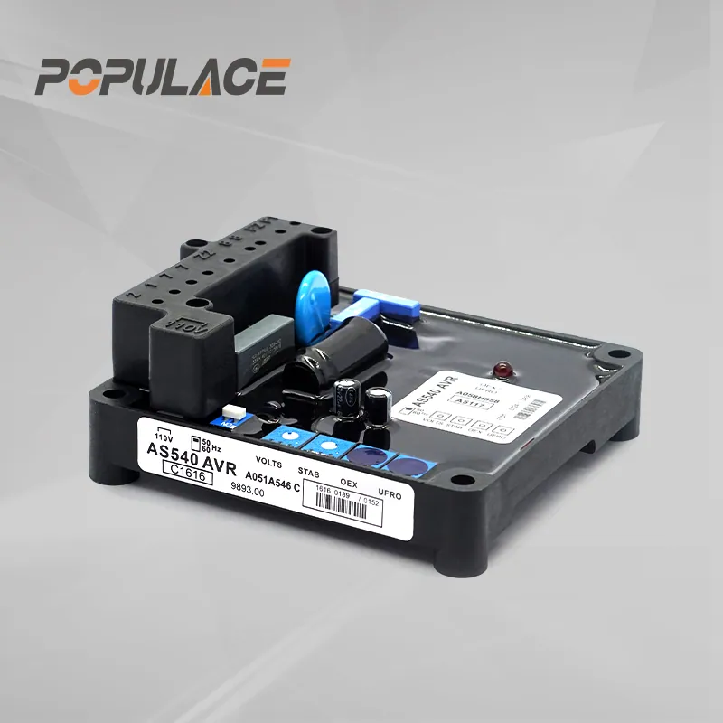
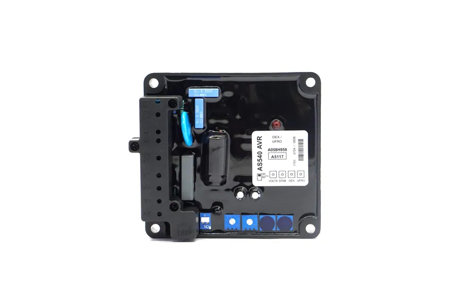
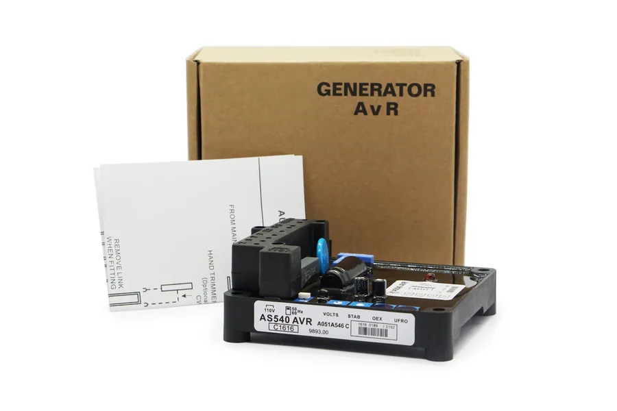
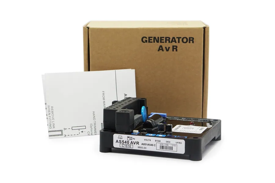
Generator Automatic Voltage Regulator Stamford AVR AS540
Model: AS540
Compatible AS540 generator AVR voltage regulator with technical manual PDF and wiring diagram. 100% bench-tested, 13-month warranty, in stock.
| Warranty | 13 months |
|---|---|
| Place of Origin | Fujian, China |
| Brand Name | POPULACE |
| Model Number | AS540 |
| Overall Size | 175×150×65mm |
| Weight | 0.38kg |
| Certification | CE,ISO9001 |
| Sensing Input | 120V / 240V AC (jumper selectable) |
| Power Input | 95-265V AC (stator or auxiliary winding) |
| Excitation Output | Max 82V DC @ 4A continuous |
| Voltage Regulation | < ±1.0% RMS (4% engine governing) |
| MOQ | 1 pc |
| Lead time | 2-3 days (in stock) |
Applications
- Standby and prime diesel generator sets fitted with Stamford alternators in telecom, data-centre and hospital backup power
- Commercial and industrial gensets requiring stable output voltage under varying load
- Alternator rewinds and rebuilds where the original AVR is obsolete or damaged
Product Description
The AS540 is a modern, analogue phase-controlled Automatic Voltage Regulator (AVR) designed for small to medium brushless AC alternators. Formed as part of the excitation system for Stamford S0 and S1 series generators, the AS540 provides closed-loop control by sensing terminal output voltage and continuously adjusting exciter field current to maintain tight steady-state regulation (< ±1.0% RMS).
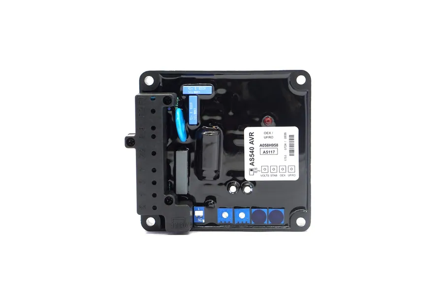
The AS540 is highly versatile, capable of deriving power from either the main stator windings or an auxiliary stator winding to enhance sustained short-circuit performance. It incorporates comprehensive protection circuitry, including Under-Frequency Roll-Off (UFRO), fixed over-voltage detection (65 VDC), and time-delayed over-excitation (EXC) shutdown with LED status indication. This POPULACE replacement module is 100% pin-compatible, dimensionally identical, and electrically calibrated to match original Stamford AS540 specifications.
Technical Specifications Matrix
| Parameter | Operating Limits & Standards | Notes & Field Conditions |
|---|---|---|
| Sensing Input | 95–130 VAC (1-phase) or 190–265 VAC (1-phase) | Jumper selectable via terminal link; 50–60 Hz |
| Power Input | 95–265 VAC 1-phase only | 50–60 Hz nominal; from stator or auxiliary coil |
| Excitation Output | Max 82 VDC @ 200 VAC input | Continuous 4A DC; Transient 7.5A for 10 s |
| Field Circuit Resistance | 15 Ω minimum (10 Ω min if input <175 VAC) | Protects output thyristor from thermal overload |
| Steady-State Regulation | < ±1.0% RMS | With 4% engine governing |
| Thermal Drift | 0.03% per °C change in ambient | Measured after 2-minute stabilization |
| Over-Voltage Detection | Fixed internal set point at 65 VDC | Internal protection circuit |
| Over-Excitation Protection | Adjustable trip threshold via [EXC] pot | Fixed 10 s to 15 s time delay; LED flashes |
| Under-Frequency Knee | 94% to 98% of nominal frequency | Factory set, selectable via on-board slide switch |
| External Volts Trimmer | ±10% with 1 kΩ 1W potentiometer | Connected across terminals 1 & 2 |
| Unit Power Dissipation | 12 Watts maximum | High-efficiency thermal profile |
| Residual Build-Up Voltage | 5 VAC minimum at AVR terminals | Below 5 VAC requires DC field flashing |
Terminal Connections & System Wiring Guide
Connections are made via 6.3 mm (1/4 inch) fast-on push-on terminals:
- Terminals 3 & 4 (Sensing & Power Input): Samples single-phase AC voltage directly from generator output terminals (95–265 VAC).
- Terminals 7 & 8 (Supply Source Selection):
- Main Stator Powered: Link fitted between terminals 7 and 8.
- Auxiliary Winding Powered: Remove link between 7 and 8. Connect auxiliary winding leads directly across terminals 7 and Z2/8.
- Terminals F1 & F2 (Exciter Field Output): Direct DC output to the exciter stator field winding. Observe strict polarity: F1 to exciter positive (+), F2 to exciter negative (-). Minimum resistance 15 Ω.
- Terminals 1 & 2 (External Volts Trimmer): Fitted with a shorting link from the factory. Remove link to connect a 1 kΩ 1W remote voltage adjustment potentiometer.
- Slide Switch (Frequency Selection): Selects between 50 Hz and 60 Hz nominal operating frequency.
Step-by-Step 4-Potentiometer Calibration Sequence
The AS540 features four precision adjustment trimmers. Complete adjustments in the following order:
- [VOLTS] — Voltage Level:
- Rotate [VOLTS] counter-clockwise prior to initial engine start.
- Start generator on no load and bring to nominal 50 Hz or 60 Hz.
- Turn [VOLTS] slowly clockwise until rated phase-to-phase terminal voltage is achieved.
- [STABILITY] — Stability & Anti-Hunting:
- With generator at rated speed, rotate [STABILITY] slowly counter-clockwise until terminal voltage exhibits hunting.
- Rotate [STABILITY] clockwise until voltage is completely stable, then advance an additional 1 to 2 small divisions.
- [UFRO] — Under-Frequency Roll-Off Knee:
- Set the on-board slide switch to match generator nominal frequency (50 Hz or 60 Hz).
- Lower engine speed to 95% of nominal frequency (47.5 Hz or 57.0 Hz).
- Rotate [UFRO] clockwise until the on-board red LED illuminates and voltage begins dropping proportionally.
- Return engine speed to 100% RPM; verify the LED extinguishes and voltage recovers.
- [EXC] — Over-Excitation Trip:
- The [EXC] control is factory-set and sealed to protect exciter components from thermal damage under prolonged overload. If recalibration is required, run at full overload threshold and adjust [EXC] until the LED turns on.
Field Troubleshooting & Diagnostic Checks
- Fault 1: Output Voltage Drops to Zero and Red LED Flashes Continuously
- Diagnosis: Over-excitation [EXC] trip or over-voltage trip activated.
- Action: Check for severe generator overload or shorted rotating diodes in the exciter rotor. To reset the AVR, stop the generator completely and restart after eliminating the cause of overload.
- Fault 2: Generator Fails to Build Up Voltage on Start-Up
- Diagnosis: Residual voltage at AVR terminals below 5 VAC, or loose sensing connections.
- Action: Measure residual voltage across terminals 3 and 4 while running. If <5 VAC, stop the set and perform DC field flashing across F1 (+) and F2 (-) using a 12V DC battery with a series-blocking diode.
- Fault 3: Voltage Rises Abnormally High and Cannot Be Controlled
- Diagnosis: Broken sensing lead or sensing jumper set incorrectly for grid voltage.
- Action: Check voltage selection link on terminals 3 and 4. Inspect wiring harness for continuity.
Generator Automatic Voltage Regulator Stamford AVR AS540 — Connection & Terminal Verification
Electrical pinouts, terminal blocks, and sensing wire inputs must match your generator panel layout before applying power.
Need help checking terminal compatibility?
Send a clear photo of your existing controller label and rear wire harness to our technical team.
Reference Schematics & Terminal Layout
Technical Manual & Documentation
Generator Automatic Voltage Regulator Stamford AVR AS540 Technical Documentation
Verified POPULACE replacement reference document
FAQ
This POPULACE unit is a 100% form-fit-function compatible replacement for the Stamford AVR AS540. It is designed for modern brushless AC alternators such as Stamford S0 and S1 frames, supporting either main stator or dedicated auxiliary winding power inputs.
The AS540 is an advanced modern successor offering upgraded over-excitation protection (EXC) with a 10-15s timer and LED diagnostic flash, auxiliary winding capability for sustained excitation during overloads, and a wider sensing voltage range (up to 265 VAC).
Yes. The complete 20-page comprehensive technical manual with terminal layouts, auxiliary winding schematics, and potentiometer calibration instructions can be downloaded immediately using the [Manual (PDF)] button on this page.
The full technical specification sheet and installation manual for AS540 are available directly via the download button above or in the Manual & FAQ tab.
On the AS540, a flashing red LED indicates that the AVR has removed excitation power following an over-excitation trip, an over-voltage condition, or sustained low engine speed under UFRO operation. Stop the generator set to reset the AVR after clearing the fault.
Yes. Output voltage, stability adjustment, over-excitation shutdown, and UFRO roll-off functions are bench-tested on every unit, and the test record travels with your order.
Stamford AVR AS540: overall size 175×150×65mm, shipping weight approx. 0.38kg. Send your panel or packing constraints and we confirm fit.
Stamford AVR AS540 is covered by a 13 months factory warranty. Quality issues within the term are replaced or repaired at our cost.
Stamford AVR AS540 carries CE,ISO9001 certification from our ISO9001-certified Xiamen facility.
Yes. POPULACE Electronic Co., Ltd. manufactures generator parts in Xiamen, Fujian - factory visits are welcome.
Yes. Samples are available for testing; express freight (FedEx, DHL, UPS, TNT, Aramex) typically delivers within 3-7 days.
In-stock items ship 2-3 days after payment; larger batches are produced in 3-7 days. Sea, air or express shipping is arranged to your preference.
T/T, PayPal, Western Union, MoneyGram, Alibaba order link and RMB transfer are all supported.
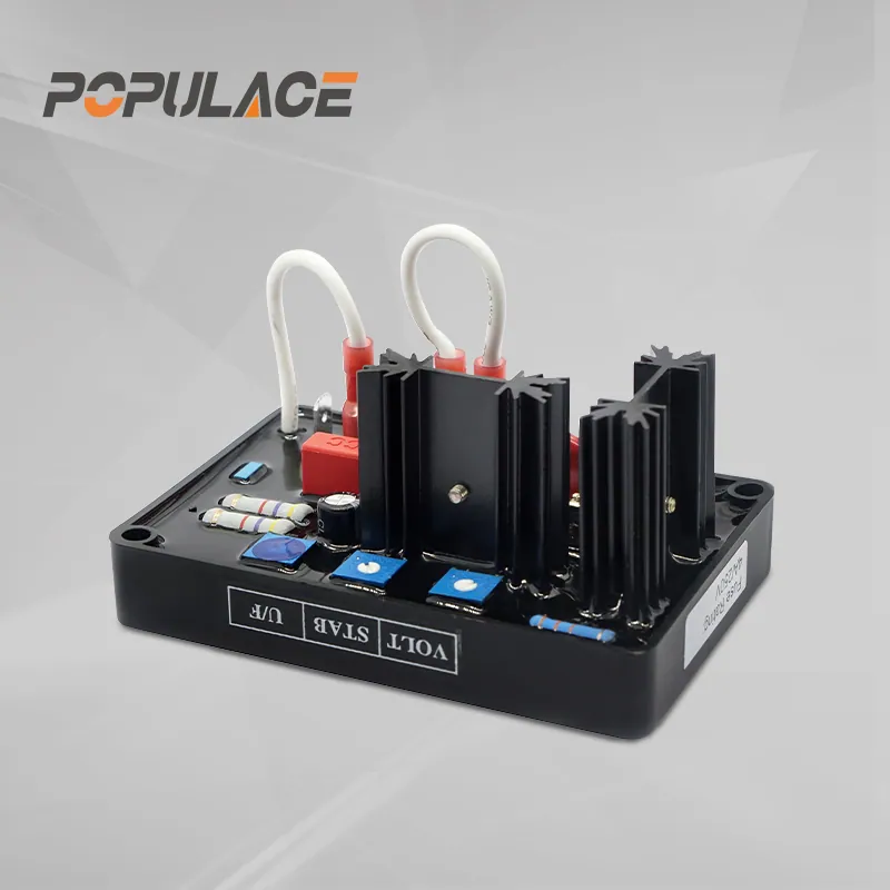
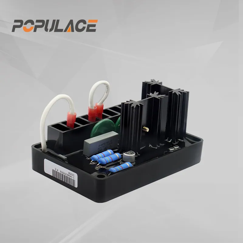
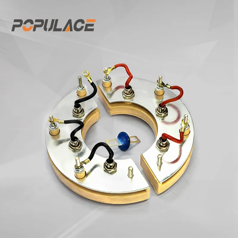
Related Products
Compatible generator parts & matching system accessories.
Technical Guides & Troubleshooting
Engineering diagnostics, terminal wiring diagrams, and parts replacement procedures.
Stamford SX460 vs MX341 vs AS480: Which AVR Does Your Alternator Really Need? (2026 Engineering Guide)
Selecting between Stamford SX460, MX341, and AS480 AVRs depends on your alternator frame, excitation source (Shunt, PMG, or EBS), and load profile. Here is the full engineering breakdown.
Read Guide → Engineering GuideGenerator AVR Not Producing Voltage: 5 Causes and How to Test Them
A generator that runs but produces no power is most often an excitation or AVR problem. Here are the five causes we see most in the field, the multimeter check for each, and when the regulator itself needs replacing.
Read Guide →20 Years Experience for Genset Parts
POPULACE has 20 years of experience supplying generator parts worldwide — reliable, OEM-compatible, and built for continuous operation.
Get a Quote